TC420 unit review
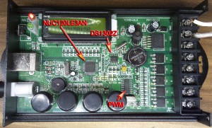
Since there was no request to send the unit back, I decided to analyze it from inside. After opening the unit, I discovered that it is controlled by the Nuvoton NUC120LE3AN MCU. On internet, I found an information that it is a component based on the ARM Cortex M0 core. Unfortunately, the ARM core is part of many processors nowadays. The ARM Cortex M0’s instruction set is nothing revolutionary.
My expectation was that the unit took care of the following tasks: generation of 5 PWMs, display control, buttons reading, communication with PC over USB and maintaining the date and time. NUC120LE3AN is in the LQFP48 package which has only four PWM channels. It is possible to use the timer for the 5th channel. To maintain the time, it is possible to use the RTC (real-time clock) modul. The small speaker on the board seems to me redundant.
However, the author of the unit had a different opinion. When I was analyzing the unit, I could not stop wondering. The first mystery was the way of the PWM signals’ generation. I only found the signal of the 4th channel (pin 25) which was generated by PWM 3. There were no PWM signals on the PWM 0, 1, 2 pins. Then I found the 5th channel signal (pin 48) which was generated by the timer (TM0). However, there were all 5 PWM signals on the MOSFETs. I continued searching and found out that from the pin 9 (TXD1) which works as a serial port with the speed of 9600 baud, 6 bytes are cyclically sent to a chip on the board. This chip has its own crystal approx. 11 MHz. From those 6 bytes, the first one is always zero followed by 5 bytes of PWM values, which the unit is sending to that chip. The chip is generating 5 PWM signals. In other words, instead of the use of the NUC120LE3AN peripherals for the 5 PWMs generation, the author is sending 5 bytes over the serial communication to another chip that is generating the PWMs.
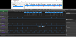
The values are sent to the other chip as follows: 0 % corresponds to 0, 100 % is sent as 250. At this value, we can measure the PWM on the output as approx. 98 %. So, 100 % is not 100 %. Why? The chip generating the PWM is probably programmed to generate the PWM of 100 % at the value of 255 (max. value of an 8-bit number). Proof: 250 / 255 x 100 = 98. The question is: Why didn’t the author use 255 as the maximum? Probably, he only used a value from the table, shifted once to the left. He took the same value and shifted it once to the right. Then he summed these two results. It means he multiplied it by 2.5. This is what the line of code could look like in the C language:
u8PWM = (u8TableValue << 1) + (u8TableValue >> 1);
where u8PWM is the resulting PWM value (0 – 250, uint8_t type) and u8TableValue is the input table value (0 – 100, uint8_t type).
While it would be sufficient to use the multiplication of 2.55 in the manner that the number 2.55 is shifted to the upper 8 bits of a 16-bit variable. It could look as follows:
u8PWM = (uint8_t)(((uint16_t)u8TableValue * (uint16_t)655) >> 8);
The constant 655 is derived form the maximum of a 16-bit number (65535) divided by 100 (PWM maximum). We can simply verify it for the value 100: 100 x 655 = 65500. This number will be shifted to the right 8 times, it means divided by 256 (or 28): 65500 / 256 = 255. It is fact, that two shifts and one addition can be much faster on some processors but this is not the case of Cortex M0. Especially, if the PWM is updated max. once per minute. Cortex M0 uses just one instruction MULS for the multiplication and, the ASRS for the shift. While in the first case there will be two instructions for the shift ASRS and one, for the addition ADDS.
Nevertheless, the current solution (with the use of 8 bits for the PWM value) could reach the resolution of 0.5 %, not 1 %. But the application on the PC side would require slight modification for that.
If the author utilized the NUC120LE3AN peripherals: PWM or timer, he could reach a lot higher PWM resolution. It would require the knowledge of the fractional arithmetic: The PWM frequency of the TC420 unit is 540 Hz. If the peripheral’s input frequency is 22.1184 MHz (as stated in NUC100/120 Technical Reference Manual), the resulting PWM period will be 22118400 / 540 = 40960 increments. This peripheral has a 16-bit counter, it means it counts to 65535. Thus, the resulting period is achievable. If we divide the base of 100 % by this period, we’ll obtain the PWM resolution in percent; it means 100 % / 40960 = 0.0024 %. I would say it is a lot far away from the resolution of 1 %, isn’t it?
Another thing that surprised me, is the existence of the Maxim DS1302Z component. Its task is to maintain the date and time. As I mentioned above, the NUC120LE3AN has the RTC modul which can be used for the date and time. It is also possible to switch the MCU into the sleep mode, to reduce the consumption, and wake it up by means of the RTC for an instant, perform the operation and switch to the sleep mode again. Why did the author use DS1302Z which requires serial communication with NUC120LE3AN? Moreover, it needs another crystal.
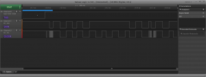
I measured the communication between the MCU and DS1302Z. I must witness I could not believe what I saw. The author wanted to probably use the I2C peripheral because the MCU uses just the I2C peripheral’s pins for the communication with DS1302Z. However, the communication that DS1302Z uses, only reminds of the I2C. In fact, it is not the I2C. The author could use the SPI peripheral with the MOSI (master out, slave in) and MISO (master out, slave in) pins shorted. In the case of reading from DS1302Z the MOSI pin would be put into the high impedance state after sending 8 bits (command) such the MISO pin could read the information.
However, the author chose a software control of the clock and data pins by controlling them as the GPIO (general purpose input output) pins. In the figure, it is possible to see a higher frequency of the clock signal and some fluctuation during the first 8 bits. At this point, it was the 0x81 command – reading of the seconds. Then a completely different frequency of the clock with some fluctuation follows. In this instant, DS1302Z responds sending the seconds in the BCD system. The author was not able to create a loop with a constant period for such primitive communication.
The PWM outputs are connected to MOSFETs in the DPAK package. I didn’t see any filters on them. So, the LED strips may have interferences. However, I didn’t check it. The USB uses the HID (human interface device) class for the communication with the PC; that’s why it is not necessary to install any driver to Windows. The HID is a basic class which already exists in Windows. This was probably copied from an example on how to make a USB HID device.
The unit could be smaller, cheaper, with lower consumption and mainly the PWM resolution would be a lot larger. In other words, if the PWM resolution spread out, the transitions between the LED intensities would be a lot finer. It would not be enough just to reprogram the unit to improve it; it would also mean modifications on the board. I think that the author should rather consider a career in politics.
Comments
Overview of comments
Yes,
I would also like the resolution to be finer than 1%, pity we can not do anything
Re: Update
Jarek, 26/4/2020 15:03I've started development of a device with the resolution of 0.001 %. See here: https://www.jarekunderwater.com/en/articles/aquasky/
TC 420
pomoc, 8/10/2018 18:40Dzień dobry mam pytanie dotyczące TC 420 a mianowicie pan opisywał środek kontrolera i na zdjęciu opisał pan nazwą PWM układ scalony mam go do wymiany i nie wiem co mam zamówić proszę o pomoc


Update
Lio, 11/7/2017 11:24